Rail Industry Evolution & Trackside Monitoring
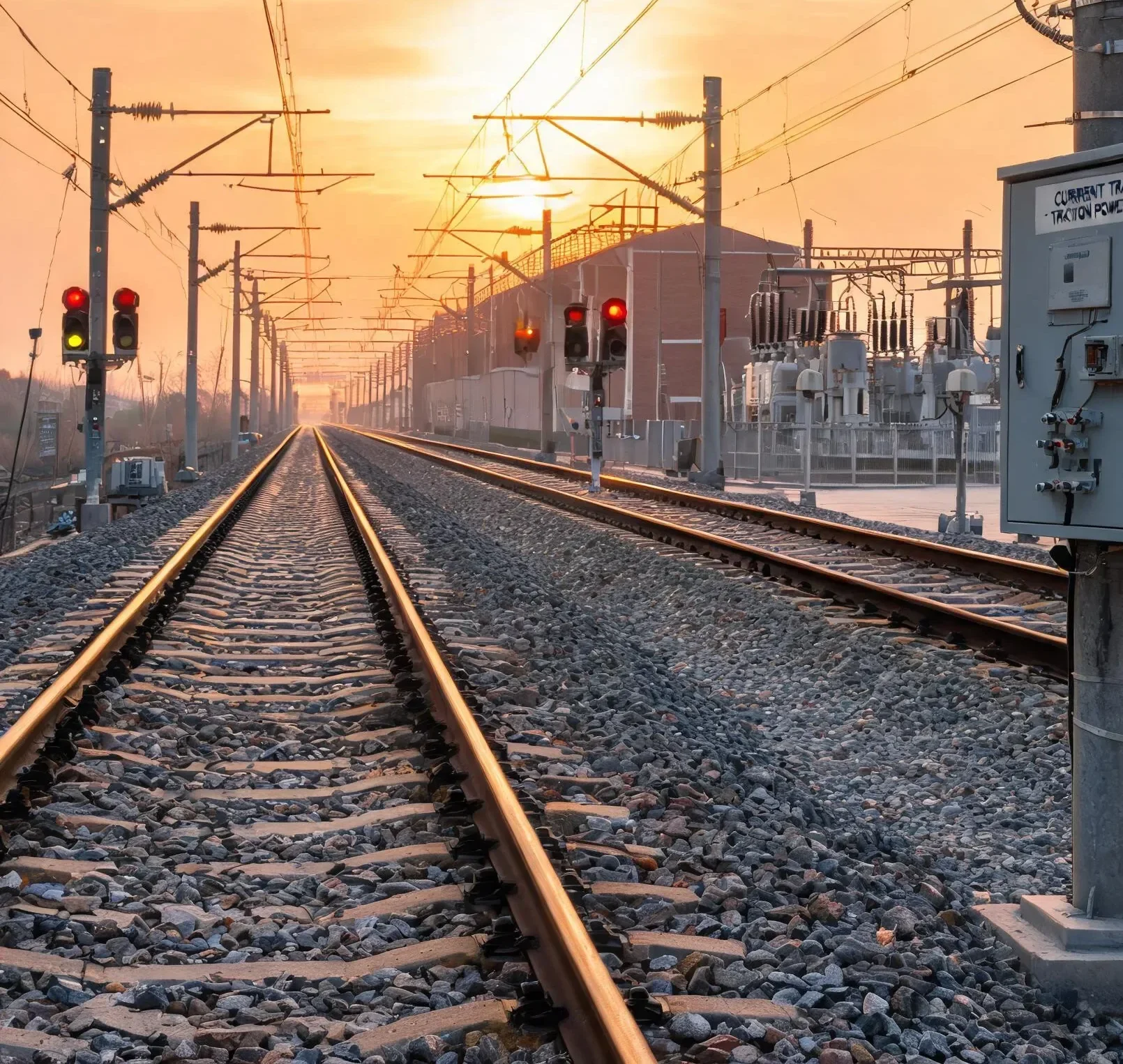
The rail industry is continually evolving. The privatization of rail networks has introduced new requirements, such as the need for rail maintenance through the monitoring of point machines (switches) and signaling conditions. LEM addresses these standards with its trackside transducer ranges, offering consistent control and protection signals for both on-board and wayside applications.
With four decades of railway experience, LEM is well-equipped to assist in adapting to these evolving technical applications, ensuring efficient, safe, and reliable operation of railways worldwide.
Typical Applications for Trackside Sensors
Key Trackside Monitoring Areas
- Point Machines: Monitoring the current of point machines helps detect mechanical issues early
- Crossing Gates: Ensuring proper operation by monitoring current usage
- Signaling Systems: Maintaining reliability by tracking current consumption
- Track Circuits: Detecting train presence by monitoring electrical circuits
- Substations: Monitoring current to manage electrical load and protect transformers
- Control & Safety Systems: Ensuring proper functioning of trackside equipment
Trackside Electric Point Motors Current Measurement
The current of the electric motor of a point machine can be measured by a current transducer and monitored. Any variation from the normal current waveform indicates an early warning of equipment failure that will require preventive maintenance. A quick scheduled maintenance intervention avoids interrupting rail traffic, resulting in significant cost savings.
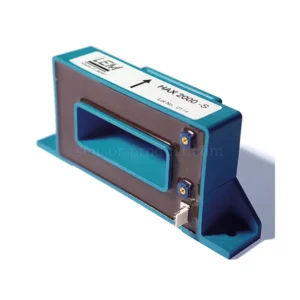
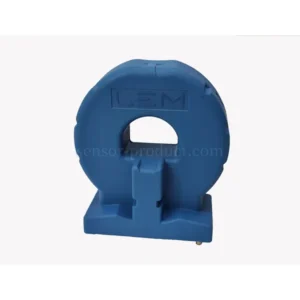
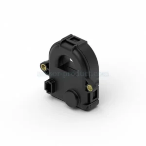
HTRS Series — Split Core Current Sensor
- 10 A – 30 A – 50 A nominal current
- DC and AC measurement capability
- 4 – 20 mA output signal
- High insulation level (> 1000 V CAT II, PD2)
- Split core design with excellent performance
- 30 kHz bandwidth
Preventive Maintenance of Point Machines
About 25% of disturbances causing train delays are due to point machines along the tracks. Their preventive maintenance, with potential replacement prior to failure, is a way of improvement thanks to condition monitoring.
Current Profile Monitoring Methodology
The output from a sensor measuring the DC (or AC) current drawn by the point motor is logged to produce an operational profile of current against time. This “footprint” forms the basis of comparison for future measurements. As time elapses, changes in this electrical footprint can indicate:
- Mechanical wear and lack of lubrication
- Jamming within the point mechanism (e.g., caused by ballast)
- Electrical motor and winding failure
- Point misalignment
- Rust, debris, or vandalism
Using current profile monitoring before problems occur, an early warning of machine failure is provided to signal preventive maintenance, optimizing maintenance staff efficiency and minimizing traffic disruption.
Trackside Product Comparison
| Parameter | HTRS | LESR | FL | FRS | PCM |
|---|---|---|---|---|---|
| Bandwidth | 30 kHz | 300 kHz | 100 kHz | 1000 kHz | 1 kHz |
| Current Range Max | 20 A | 20–150 A | 42 kA | 9000 A | 25–30 A |
| Supply Voltage | 24 V | 5 V | 12–24 V | 12–24 V | 24 V |
| Mounting | Panel | PCB | On Primary | On Primary | Panel |
| Accuracy | 2%–5% | 0.5%–0.7% | 0.5% | 0.65% | 1%–2% |